In this project, we are using a water
level alarm using simple and low cost hardware using a 555 timer
circuit. The aim of this project is to make a water level detecting
alarm with simple and low cost hardware without compromising on the
performance of the device.
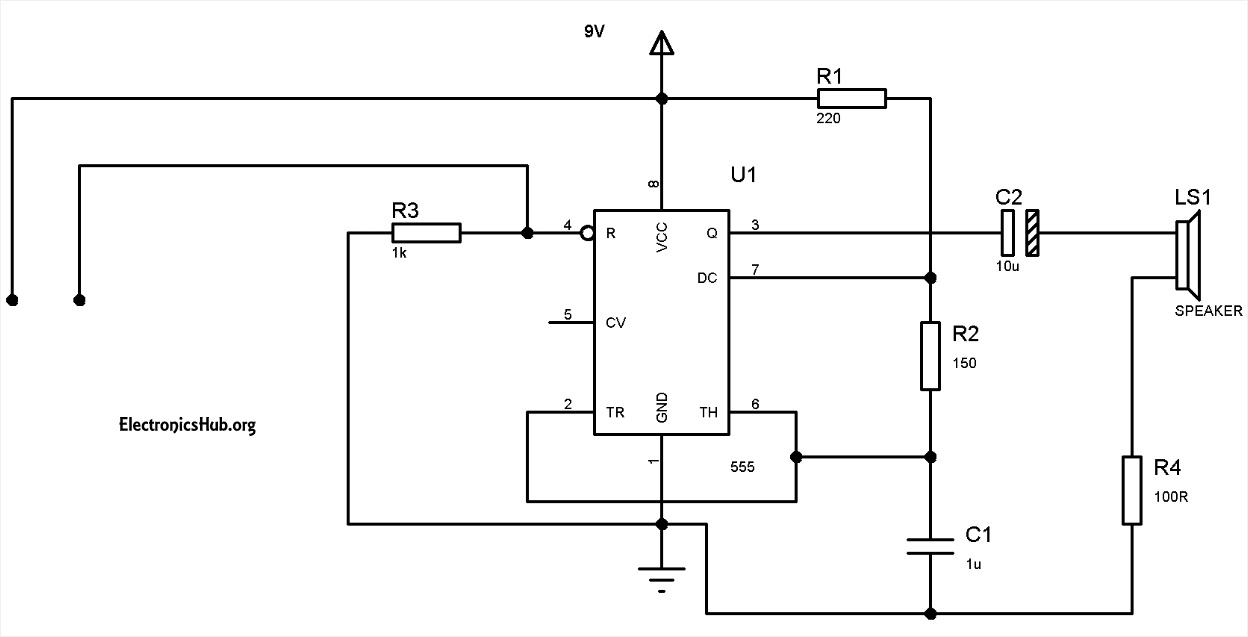
Water Level Alarm Using 555 Timer Circuit Diagram:

The circuit uses a 555 timer in astable
mode with R1=220 ohms, R2= 150 ohms and C1=1 uF. As we know, the
frequency of operation of the IC 555 in astable mode depends on the
values of R1, R2 and C1. By calculating the frequency of the given
astable circuit, we get the frequency to be around 1.18KHz. The
frequency at which it operates is in the audio frequency.
The 1K Resistor R3 whose ends are
connected to pin-4 and ground disables the circuit by default and it
enables when the water reaches its full level when the probes get dipped
in water.
The two probes which are shown in the
circuit should be kept at the high level for the water. The astable
multivibrator in the circuit is normally disabled and it gets enabled
only when the probes touch the water. The distance between the probes
should be less than a few centimeters to ensure that the conduction
between the probes will take place when water is touched to these
probes. When the water level rises to the height of the probes, then the
555 circuit will get enabled and the output of the 555 timer produces a
square wave output with a frequency of about 1.18Khz. This output is
given to the mini loudspeaker which then beeps at an audio frequency of
1.18KHz.
No comments:
Post a Comment